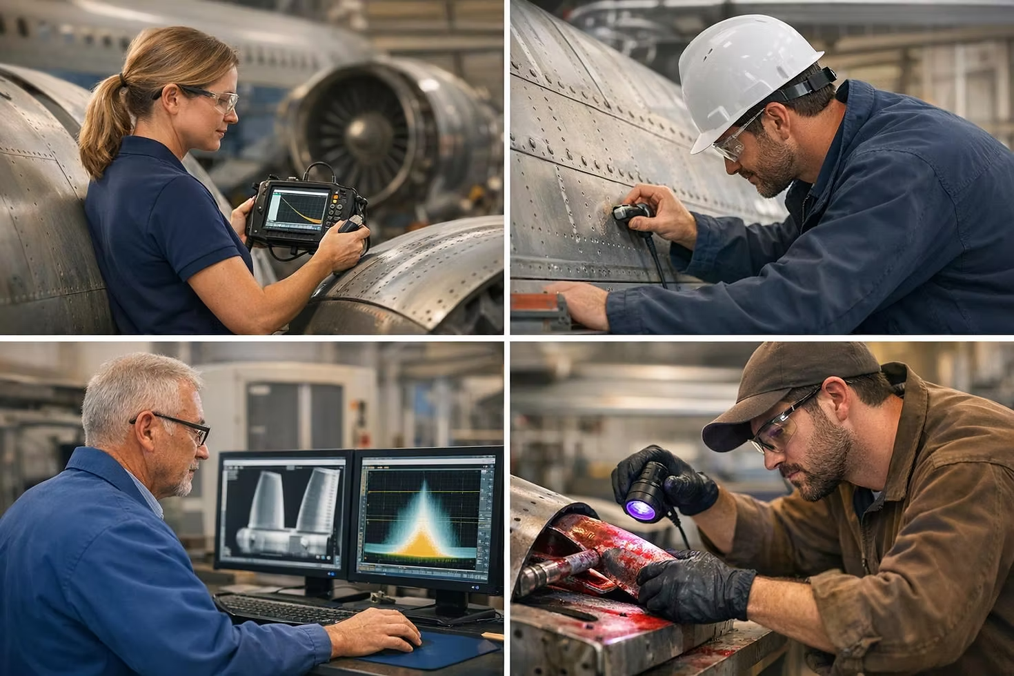
Aerospace fabrication demands rigorous inspection to ensure safety and quality. Framos (Fabrications) Ltd outlines five key methods used to detect defects in materials and components, each suited to specific scenarios:
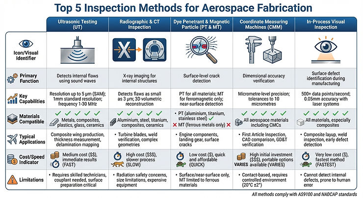
- Ultrasonic Testing (UT): Uses sound waves to find internal flaws like cracks and delaminations in metals and composites.
- Radiographic and CT Inspection: X-ray-based methods for detailed internal imaging, ideal for complex geometries and defect detection.
- Dye Penetrant and Magnetic Particle Testing (PT & MT): Surface-level inspections for cracks and discontinuities, particularly in ferrous and non-ferrous materials.
- Coordinate Measuring Machines (CMM): Ensures dimensional accuracy by comparing parts against CAD designs, critical for tight tolerances.
- In-Process Visual Inspection: Identifies surface issues during manufacturing, preventing defective parts from advancing.
Each method plays a role in maintaining safety and compliance with aerospace standards, balancing precision, material compatibility, and cost-effectiveness. Read on for detailed insights into their applications and benefits.
- Ultrasonic Testing (UT)
Ultrasonic Testing (UT) involves transmitting high-frequency sound waves into a material using a transducer. When these waves hit a boundary or defect – like a crack, void, or delamination – they bounce back to the transducer. By analysing the time it takes for the signal to return and its strength, inspectors can pinpoint the depth, size, and location of internal flaws.
Defect Detection Capability
UT is particularly effective at identifying cracks, delaminations, voids, and variations in thickness. According to the National Physical Laboratory: “Ultrasonic C-scan is used to detect, measure and characterise a wide range of manufacturing and in-service defects in composite materials, and is routinely used in the aerospace industry.”
NASA’s Advanced Composites Project has refined UT protocols, covering 88 NDE standards to address common composite defects. Advanced Scanning Acoustic Microscopy (SAM) can provide extremely fine spatial resolution – up to 5 microns – with a beamwidth of 120 microns. Meanwhile, standard ultrasonic C-scan systems achieve 1 mm resolution over areas as large as 650 x 650 mm.
Cost and Accessibility
UT is not only technically capable but also offers practical advantages in aerospace inspections. It provides immediate results, supports real-time quality control, and requires minimal preparation of the test specimen. Thickness measurements are highly accurate, often within 0.1 mm. Since UT can inspect components from just one side, it’s particularly useful for complex structures. The equipment is also relatively affordable, adding to its appeal for aerospace applications.
- Radiographic and Computed Tomography (CT) Inspection
Building on the focus of non-destructive evaluation, radiographic and CT inspection techniques use X-rays to reveal the internal structures of aerospace components. While traditional 2D X-ray imaging provides flat projection images, 3D CT scanning goes a step further by creating detailed volumetric reconstructions through hundreds of X-ray images taken from various angles. Together, these methods play a vital role in ensuring comprehensive quality control alongside other inspection approaches.
Material Compatibility
Radiographic and CT inspections are highly adaptable, capable of evaluating a wide range of aerospace materials
Cost and Accessibility
The shift from film-based radiography to digital systems has brought notable cost savings. Gary Reay, an NDT Engineer at Leonardo, explains: “digital radiography… offered a big cost saving in terms of consumable materials, disposal of waste, and storage of images.”
Digital radiography also provides faster results, sharper image quality, and improved traceability for critical components like rotor assemblies. The integration of AI and machine learning is further transforming the field by speeding up defect identification and reducing reliance on highly trained personnel. However, inspections involving high-energy CT systems require significant shielding, which can limit the size of samples. While these systems represent a considerable investment, their importance in modern aerospace manufacturing continues to grow.
Application in Aerospace Fabrication
Thanks to their precision and material compatibility, radiographic and CT inspections are indispensable throughout the aerospace manufacturing and maintenance lifecycle. They are used to verify raw materials, monitor processes like welding or additive manufacturing (spotting defects such as porosity in real time), ensure final product quality, and conduct post-failure analyses. In maintenance and repair, these methods allow for non-invasive evaluation of critical components like turbine blades, detecting fatigue and damage without dismantling the engine. For challenging applications, such as inspecting honeycomb structures or turbine blades, CT provides a distinct advantage by generating detailed 3D visualisations of internal geometries without requiring surface contact or coupling gels.
- Dye Penetrant and Magnetic Particle Testing (PT and MT)
While radiographic and CT methods are excellent for uncovering internal structures, dye penetrant testing (PT) and magnetic particle testing (MT) specialise in identifying surface and near-surface defects. These tried-and-true techniques have long been staples in aerospace manufacturing due to their straightforward approach and reliability. Ben Sampson, Editor of Aerospace Testing International, highlights their importance: “Liquid penetrant testing is one of the most commonly used NDT techniques.”
Both methods play a crucial role in verifying visually detected flaws before moving on to more in-depth inspections. Here’s how each method works, its material compatibility, cost considerations, and specific applications.
Defect Detection Capability
PT involves applying a dye or fluorescent liquid to a surface. This liquid seeps into surface-breaking flaws such as cracks or fissures. A developer is then used to draw the liquid back out, making these imperfections visible under normal or ultraviolet light. On the other hand, MT focuses on ferromagnetic materials. By magnetising the material, it creates a magnetic field, and any disruptions – caused by cracks or other discontinuities – cause iron particles to cluster at the defect sites.
The primary difference lies in the depth of detection. PT is limited to surface-breaking defects, while MT can identify both surface and near-surface issues, making it especially useful for critical ferrous parts like landing gear. As Sky Aircraft Maintenance explains: “MPI is a method we utilise to identify surface and near-surface discontinuities in ferromagnetic materials. By magnetising the component and applying ferrous particles, we can visualise the imperfections, a key component in maintaining the robustness of parts such as engine components or landing gear.”
Material Compatibility
The choice between PT and MT depends on the magnetic properties of the material. MT is exclusively for ferromagnetic materials, such as the iron and steel used in landing gear and fasteners. PT, however, is suitable for a broader range of materials, including aluminium, titanium, stainless steel, and non-porous composites. Voliro notes: “Non-ferromagnetic materials like stainless steel, aluminium, or non-ferrous alloys can be tested with penetrant testing. This testing method also works better for structural components with irregular shapes.”
PT is particularly effective for inspecting complex geometries – like turbine blades, engine parts, or curved piping – since the liquid can penetrate intricate shapes. However, cleanliness is critical for both methods. Any grease, oil, or dirt must be removed beforehand, as these contaminants can interfere with the results. Additionally, attempting MT on non-magnetic materials, such as aluminium, will produce no results.
Cost and Accessibility
Both PT and MT are relatively inexpensive. PT relies on simple dye-based materials, while MT uses magnetic fields and iron particles, avoiding the need for complex equipment. Avior explains: “Fluorescent Penetrant Inspection (FPI) uses a dye or liquid applied to the surface… This type of NDT is quick and affordable, but it only finds surface defects.”
PT is one of the most cost-efficient methods for aerospace manufacturing and is often integrated into routine maintenance. Portable tools for both PT and MT make them viable for on-site inspections in workshops or hangars. Despite their simplicity, compliance with industry standards, such as Nadcap approval, is usually required to meet the stringent quality demands of major OEMs.
Application in Aerospace Fabrication
PT is commonly used for inspecting turbine blades, engine components, and aluminium skins, while MT is ideal for examining landing gear, steel fasteners, and engine mounts. For critical components, fluorescent penetrants or magnetic particles that glow under ultraviolet light are often used to enhance detection sensitivity. These methods depend heavily on the inspector’s expertise and keen observation, particularly with PT, which requires precise lighting conditions. While PT and MT lack the depth capabilities of radiography or ultrasonic testing, they remain essential tools for quick surface inspections and early defect identification.
- Coordinate Measuring Machines (CMM) and Precision Metrology
While earlier methods focus on identifying flaws and discontinuities, Coordinate Measuring Machines (CMMs) take things a step further by verifying dimensional accuracy. These advanced systems generate digital models that can be directly compared to original CAD designs and Geometric Dimensioning and Tolerancing (GD&T) standards. In industries like aerospace, where tolerances often reach as tight as 10 micrometres – thinner than a strand of human hair – CMMs ensure components meet exact specifications. As Measurement Solutions puts it: “Precision counts. Whether you’re meeting stringent guidelines in the aerospace industry, or joining the dots between manufacturing facilities in a multi-partner project, precision matters.”
This focus on precision complements earlier non-destructive testing (NDT) methods, offering a more comprehensive approach to quality control.
Defect Detection Capability
CMMs are exceptional at capturing surface geometry with micrometre-level precision. 5-axis systems stand out by synchronising movements to minimise dynamic errors, while multi-sensor setups allow for seamless switching between tactile scanning, touch-trigger, and vision sensors – all without needing to reposition the part. Renishaw highlights the advantages: “5-axis measurement technology delivers unprecedented measuring speed and flexibility, whilst avoiding the speed versus accuracy compromises inherent in conventional techniques.”
This makes CMMs particularly valuable for First Article Inspection (FAI), where the first production run undergoes verification before moving to mass production.
Material Compatibility
CMMs are compatible with a wide range of aerospace materials, including aluminium, titanium, steel, carbon fibre composites, and Ceramic Matrix Composites (CMCs). The choice of probing system is crucial here: tactile probes work best with rigid, machined metal parts, while non-contact laser or optical probes are ideal for fragile or complex freeform surfaces. FARO underscores this adaptability: “Regardless of whether you work with metal, wood or any other material… our mobile coordinate measuring machines (CMMs) are ideal for checking component quality during production.”
To achieve the highest precision, measurements require controlled environments at 20 degrees C (plus or minus 2 degrees), and surfaces must be clean to avoid errors.
Application in Aerospace Fabrication
CMMs play a crucial role in meeting aerospace industry standards like AS9100 and NADCAP AS7003. They ensure that critical dimensions match design specifications, and automated CMMs further enhance efficiency by reducing manual errors and speeding up production in high-volume environments. These systems also create digital records for traceability, which is vital for managing quality and meeting regulatory requirements. In the UK alone, CMMs inspect products valued at over GBP 100 million annually. For aerospace manufacturers, CMMs provide the precision needed to meet demanding standards while maintaining production efficiency.
- In-Process Inspection and Visual Checks
In-process inspection and visual checks offer a simple yet highly effective way to maintain quality control during manufacturing. Unlike waiting until a product is fully fabricated, these methods catch errors as they happen, stopping defective components from progressing further. As the Health and Safety Executive notes: “Non-Destructive Testing (NDT) is a primary recovery mechanism for errors in design, construction and operational activities.”
This hands-on approach not only reduces the likelihood of errors but also sets the groundwork for more detailed defect analysis later in the process.
Cost and Accessibility
In-process inspections can deliver major cost savings. On-machine measurements allow for immediate detection of deviations, cutting down on expensive rework. At Embraer Executive Jets Inc., Manufacturing Engineer Scott Groves highlighted the benefits of laser inspection systems: “The time savings have been remarkable, our technicians in the paint booth can now layout an aircraft in four hours with two technicians when it used to take 2-3 shifts when working with Mylar templates. Also, the amount of rework has almost been eliminated.”
Laser-guided assembly systems are also incredibly efficient, with initial alignment being 20 times faster than traditional methods and re-alignments reduced to mere seconds. Even basic tools like calipers, micrometers, and gauges remain invaluable for quick dimensional checks due to their affordability and ease of use.
Application in Aerospace Fabrication
In aerospace manufacturing, in-process inspections are crucial for ensuring that defects beyond a certain size are caught during fabrication. These results feed directly into Engineering Critical Assessments (ECA) to evaluate whether a component is fit for purpose. The National Composites Centre emphasises this point: “In response to the challenge of manufacturing large structures without costly defects, NCC linked multiple advanced technologies into a robust, real-world manufacturing system.”
Comparing the Methods
Ultrasonic Testing identifies internal flaws, measures thickness, and works with a range of materials, but requires skilled technicians, a couplant such as water or gel, and is affected by surface conditions. It’s typically used in composite wing production and critical structural integrity checks.
Radiographic and CT inspection provides detailed internal views, with CT delivering 3D imaging for complex parts. It involves radiation safety concerns, costly equipment, and size limitations for certain parts. It’s typically used for weld inspections in pressure vessels and evaluating complex internal geometries.
PT and MT: PT detects fine surface cracks and MT offers fast results for ferrous metals, but both are limited to surface or near-surface flaws, MT only works with ferrous materials, and PT requires thorough cleaning. They’re typically used on engine components and for detecting cracks on aircraft metal surfaces.
CMM and metrology provides precise dimensional data and validates geometric features, though it’s often contact-based and slower for complex full-field scans compared to optical methods. It’s typically used for quality control on regulated parts and assembly verification.
Conclusion
Aerospace fabrication demands meticulous inspection methods to guarantee both safety and quality. Each technique serves a specific purpose: dye penetrant testing identifies surface cracks, while ultrasonic testing detects hidden internal flaws. Together, these methods provide thorough coverage, whether inspecting ferromagnetic engine parts or intricate composite structures.
What are the differences between ultrasonic testing and radiographic inspection for detecting internal defects?
Ultrasonic testing and radiographic inspection are two powerful tools used to uncover internal defects in aerospace fabrication, yet they operate in fundamentally different ways. Ultrasonic testing relies on high-frequency sound waves, which travel through a material and reflect back when they encounter flaws. These reflections help identify irregularities like cracks or voids, especially in thicker materials.
On the other hand, radiographic inspection uses X-rays or gamma rays to generate detailed images of a material’s interior. This method visually highlights imperfections, making it ideal for examining internal structures with precision.
Both methods are non-destructive and highly accurate, but their strengths differ. Ultrasonic testing is often the go-to for thicker materials where pinpointing specific defects is critical, while radiographic inspection shines when a clear visual representation of the internal structure is needed. Ultimately, the choice depends on factors like the type of material, the size of the defect, and how accessible the area is for inspection.
How do the costs of advanced CT scanning compare to traditional dye penetrant testing in aerospace inspection?
The cost differences between advanced CT scanning and traditional dye penetrant testing can vary widely, depending on factors like the inspection’s complexity, the equipment involved, and the project’s scale. Generally, advanced CT scanning comes with a higher price tag due to its cutting-edge technology and ability to produce detailed 3D images. This makes it particularly effective for uncovering internal defects in intricate components. On the other hand, dye penetrant testing is a more budget-friendly option, suited for surface-level inspections, though it falls short when it comes to detecting internal issues.
When choosing between these methods, it’s essential to balance the high precision and in-depth analysis of advanced CT scanning with the lower costs and faster application of traditional dye penetrant testing. Your decision should ultimately depend on your project’s specific needs and financial constraints.