Product quality is key for customers and when joining metal components together it is critical that the joint is strong. Each joint needs to withstand the rigours of its working environment throughout a vehicle’s life.

Whether the joint is for a tube to a bracket or end fitting, or a tube to another tube, will determine what kind of jointing method will be required.
Welding is typically used for strength on components including brackets, and for larger fabricated tubular assemblies.
Welding is a very consistent and repeatable process which can be carried out either manually or by robot. However, there is a higher risk of potential leak paths, particularly if joining two tubes together.
In this instance we would use a tack weld to locate the two components and then these would be brazed together using a filler material.
Brazed joints provide great integrity and reduce the risk of leaking parts.
Lander has in-house mild steel brazing furnaces at both our Birmingham and Franklin (NC, USA). This means that we can provide our customers with lower cost brazing solutions to deliver high quality joints.
For joining aluminium components, we have a team of highly skilled brazing technicians who are experienced in producing consistently strong brazed joints with a good aesthetic appearance. We also use in-line rotary flame brazing machines for the brazing of aluminium connector blocks to the ends of tubes.
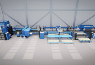
In addition to this, we also have a full fabrication line at our Malvern facility, that has the capability to produce complex assemblies including fabricated tubes up to 12 inches in diameter. These products are used in Industrial power generation so need to be robust in order to work continuously.
The slightest leak in a joint could cause at best a failure in the system or at worst it could result in a catastrophic thermal event. To ensure that this does not occur it is necessary to test each part for any leaks during the production process.
At Lander, we use air decay testing as our standard leak test process, this is done by loading the finished part into a fixture and attaching connectors to the end of the tubes and any other exposed opening. Once in place air is pumped through the pipe at pressure, then there is a period of stabilisation before the leak test is carried out using a very accurate reader to gauge the pressure. Any leak in the assembly would cause the pressure to be lower than the set levels and would constitute a failure.
Another method of leak testing is to block off all openings in the tube and then filling it will air. Once filled the tube is submerged into a water bath and then an operator will check the part for visible air bubbles. If persistent air bubbles can be observed from one point on the assembly then this would indicate a leak path and the part would be a reject.
The air decay testing method is more robust as it is less likely to be subject to human error. If the operator carrying out the underwater leak testing fails to observe a set of bubbles and the leak path then it is possible that they will then pass this part as ok and it will be shipped to the end customer.
The air decay test method registers every test in the system’s computer and this means that there is greater traceability for any failures. This data is used to ,monitor the effectiveness of the system and can be utilised during lessons learnt sessions to ensure that quality is being built into every new process.
Leak testing helps to ensure that only products of the highest quality are sent to the end customer.