In switchgear and control panel design, busbars play a fundamental role—acting as the primary distribution path for high currents between incoming supplies and outgoing circuits.
While often treated as a straightforward component, both the material selection and the quality of fabrication directly influence system performance, efficiency, and long-term reliability.
Why Copper Remains the Preferred Choice
Although aluminium is sometimes used as a lower-cost alternative, copper continues to be the benchmark material in high-current applications.
This is primarily due to its high electrical conductivity, which is among the best of any engineering metal. In practical terms, this allows for reduced resistive losses and supports more compact panel designs.
Copper also offers more stable behaviour under thermal cycling. Compared to aluminium, its lower coefficient of thermal expansion reduces the likelihood of joint relaxation over time—an important factor in maintaining consistent contact resistance and avoiding overheating.
From a durability perspective, copper provides good inherent corrosion resistance through the formation of a natural oxide layer. Where required, surface treatments such as tinning or silver plating are commonly used to further reduce oxidation at contact interfaces and maintain conductivity.
Mechanically, copper performs well under fault conditions. During short circuits, busbars are subjected to significant electromagnetic forces. Copper’s strength and stiffness help resist deformation, supporting the structural integrity of the system during these events.
The Importance of Fabrication Quality
In real-world panel layouts, busbars must be shaped to fit within constrained spaces, align with connection points, and minimise unnecessary joints.
Reducing the number of joints is beneficial, as each interface introduces additional contact resistance and potential heat generation. However, forming copper correctly is critical—poor bending practices can introduce their own risks.
Common issues include:
- Work hardening and cracking at the bend
- Localised thinning at the outer radius
- Misalignment of holes and connection points
- Increased thermal stress at poorly formed sections
Precision during fabrication is therefore essential to ensure long-term performance.
Key Considerations When Bending Copper Busbars
Accurate Length and Bend Calculations
When a busbar is bent, the outer fibres are stretched while the inner fibres are compressed. The neutral axis shifts depending on the material and bend conditions.
In practice, accurate fabrication relies on bend allowance calculations, typically using a K-factor in the region of 0.3–0.5 for copper, rather than simplified rules of thumb. This ensures that final dimensions and hole positions remain correct after forming.
Selecting the Appropriate Bend Type
Different applications require different bending approaches:
- Flatwise bends (across the wide face) are the most common and easiest to control
- Edgewise bends (along the narrow edge) are more prone to instability and require careful support to avoid buckling or twisting
- Offset bends are used to move the busbar between planes while maintaining alignment
Each type places different stresses on the material and must be executed accordingly.
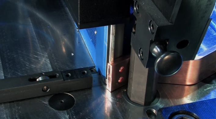
Using Suitable Tooling
Consistency and repeatability depend heavily on the equipment used.
Purpose-built systems such as the EHRT EB 40 busbar bending machine are designed specifically for precision busbar forming. The EB 40 delivers controlled, consistent force throughout the bending process, achieving angular accuracy of up to 0.2°, which enables highly repeatable results across multiple components.
By using dedicated bending equipment, bends can be formed with appropriate radii and uniform deformation, helping to minimise material stress and preserve structural integrity. This level of control is particularly important when working to tight tolerances, where consistency between parts and reliable alignment during assembly are essential.
Compared to manual or improvised methods, this approach supports higher dimensional accuracy and a more consistent finish, contributing directly to the overall quality and reliability of the finished installation.
Maintaining Bend Integrity
The quality of a bend is a clear indicator of process control.
A smooth, uniform surface suggests that the material has been formed within acceptable limits. In contrast, a rough “orange peel” appearance typically indicates excessive strain, often caused by too tight a bend radius or overly rapid forming.
As a general guideline, the internal bend radius is typically at least equal to, and often greater than, the material thickness, depending on the copper temper and application requirements.
Accounting for Bend Allowance and Alignment
Accurate bend allowance is essential to ensure that hole patterns and connection points align correctly after forming.
Even small deviations at the bending stage can lead to installation challenges, increased stress at connections, or the need for rework—all of which impact both performance and project timelines.
From Fabrication to Long-Term Reliability
Switchgear and control panels are expected to operate reliably over long service lives, often in environments where maintenance access is limited.
Copper provides the electrical and mechanical performance required to handle continuous load, thermal cycling, and fault conditions. However, these advantages are only fully realised when fabrication is carried out with precision.
Accurate bending, appropriate tooling, and integration with digital design systems all contribute to consistent, repeatable results.
In practice, copper defines the capability—but precision in fabrication defines the outcome.
How are you seeing busbar manufacturing evolve? Are digital tools and automated systems becoming standard in your projects?